Trip to Indonesia: 230kV Transmission Project
P.T. Freeport, Timika in Irian Jaya
P.T. Freeport, Timika in Irian Jaya

A ECE engineer traveled to the Indonesian jungle to design, oversee the installation, and provide quality assurance during testing for a 230,000 volt underground cable circuit located in Irian Jaya. Irian Jaya is the eastern-most province of Indonesia and borders New Guinea.
The 2.1 km cable link avoiding interference with air traffic for the airport near the village of Timika from an overhead line being built in the area.
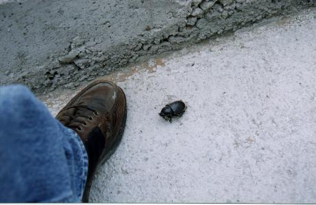
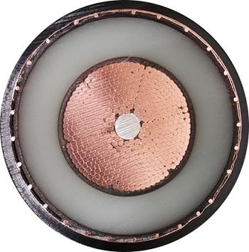
230kV cross-linked polyethylene (XLPE) cable manufactured by Olex Cables of Melbourne, Australia was used for the underground part of the circuit. A special jacket configuration consisting of a layer of nylon on top of a conventional polyethylene jacket was specified to prevent indigenous termites from eating the polyethylene. The site engineer had to put up with all sorts of friendly creatures including the elephant beetle shown in the photo.
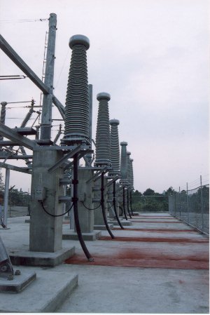
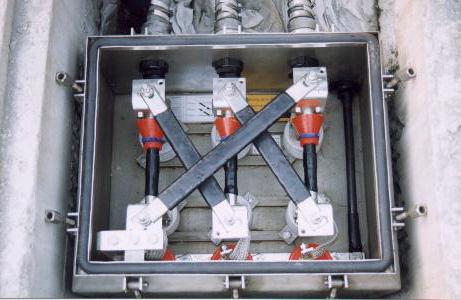
Because of dust from vehicle traffic on a nearby dirt road, high humidity, and air pollution from fires started by the Irianese, terminations with a Class IV pollution rating were used. The owner wanted to have a low maintenance system and was concerned about tracking that might occur on the terminations if they were not capable of operating for extended periods under such conditions.
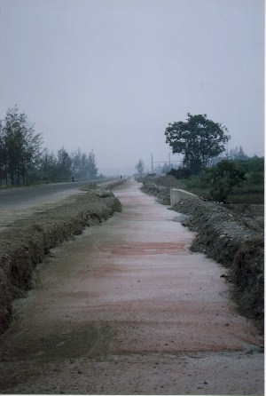
The cable route ran parallel to a service road. The native soil properties along the route were challenging from a cable engineering standpoint. At a typical cable depth of 1 meter, most of the cable would be close to the water table. Soils were granular (sandy gravel to gravely sands) such that there was high porosity in many areas. The nature of the soil meant that it had limited ability to retain water, resulting in fairly high thermal resistivities when the soil was above the water table. To optimize the cable design and minimize the effects of the native conditions, a fluidized thermal backfill (FTB) was used for the entire circuit length. A concrete cap was placed on top of the FTB to provide mechanical protection and prevent dig-ins.

In anticipation of future increases in load and to better monitor the thermal performance of the cable circuit, a multi-mode optical fiber was installed along one of the cable phases so that distributed temperature sensing could be performed at a later date.
The circuit length and limitations on shipping lengths meant that each of the 6 phases (two 3-phase circuits) had two splices. Cross-bonding was used on the circuit to reduce induced sheath currents and maximize the cable rating.
If you would like to know more, please contact Rusty Bascom at ECE.
Send mail to info@ec-engineers.com with questions or comments about this web site.
Copyright © 2026 Electrical Consulting Engineers, P.C.
Last modified: March 2026
[MOBILE]
Copyright © 2026 Electrical Consulting Engineers, P.C.
Last modified: March 2026
[MOBILE]